
Introduction
Managing arduino projects can be a nightmare because you only see the software side in your code documentation, the hardware is hard to keep track off.
To enable easy documentation of pin assignments, I created a couple of ASCII art arduinos; complete with ports, PWM and coms all marked. Simply paste as a comment into your code and marvel at your new found organisation.
I suggest altering the image (eg. a letter or X in the [ ]) to keep track of the pins you ended up using.
Find this project on gitHub
Plain Text – Arduino Pinout
Here is copy/paste-able Arduino Pinout ASCII art ready to go (tip: you can use the copy button, at the top of each ASCII art piece, to make the process easy).
I place them in the Creatice Commons [Creative Commons Attribution (BY) license].
Attribution via the url: “http://busyducks.com/ascii-art-arduinos”
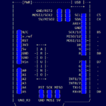
                                      +-----+
         +----[PWR]-------------------| USB |--+
         |                            +-----+  |
         |         GND/RST2  [ ][ ]            |
         |       MOSI2/SCK2  [ ][ ]  A5/SCL[ ] |   C5
         |          5V/MISO2 [ ][ ]  A4/SDA[ ] |   C4
         |                             AREF[ ] |
         |                              GND[ ] |
         | [ ]N/C                    SCK/13[ ] |   B5
         | [ ]IOREF                 MISO/12[ ] |   .
         | [ ]RST                   MOSI/11[ ]~|   .
         | [ ]3V3    +---+               10[ ]~|   .
         | [ ]5v    -| A |-               9[ ]~|   .
         | [ ]GND   -| R |-               8[ ] |   B0
         | [ ]GND   -| D |-                    |
         | [ ]Vin   -| U |-               7[ ] |   D7
         |          -| I |-               6[ ]~|   .
         | [ ]A0    -| N |-               5[ ]~|   .
         | [ ]A1    -| O |-               4[ ] |   .
         | [ ]A2     +---+           INT1/3[ ]~|   .
         | [ ]A3                     INT0/2[ ] |   .
         | [ ]A4/SDA  RST SCK MISO     TX>1[ ] |   .
         | [ ]A5/SCL  [ ] [ ] [ ]      RX<0[ ] |   D0
         |            [ ] [ ] [ ]              |
         |  UNO_R3    GND MOSI 5V  ____________/
          \_______________________/

		  http://busyducks.com/ascii-art-arduinos
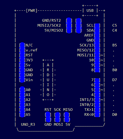
                                      +-----+
         +----[PWR]-------------------| USB |--+
         |                            +-----+  |
         |           GND/RST2  [ ] [ ]         |
         |         MOSI2/SCK2  [ ] [ ]  SCL[ ] |   D0
         |            5V/MISO2 [ ] [ ]  SDA[ ] |   D1
         |                             AREF[ ] |
         |                              GND[ ] |
         | [ ]N/C                        13[ ]~|   B7
         | [ ]IOREF                      12[ ]~|   B6
         | [ ]RST                        11[ ]~|   B5
         | [ ]3V3      +----------+      10[ ]~|   B4
         | [ ]5v       | ARDUINO  |       9[ ]~|   H6
         | [ ]GND      |   MEGA   |       8[ ]~|   H5
         | [ ]GND      +----------+            |
         | [ ]Vin                         7[ ]~|   H4
         |                                6[ ]~|   H3
         | [ ]A0                          5[ ]~|   E3
         | [ ]A1                          4[ ]~|   G5
         | [ ]A2                     INT5/3[ ]~|   E5
         | [ ]A3                     INT4/2[ ]~|   E4
         | [ ]A4                       TX>1[ ]~|   E1
         | [ ]A5                       RX<0[ ]~|   E0
         | [ ]A6                               |
         | [ ]A7                     TX3/14[ ] |   J1
         |                           RX3/15[ ] |   J0
         | [ ]A8                     TX2/16[ ] |   H1
         | [ ]A9                     RX2/17[ ] |   H0
         | [ ]A10               TX1/INT3/18[ ] |   D3
         | [ ]A11               RX1/INT2/19[ ] |   D2
         | [ ]A12           I2C-SDA/INT1/20[ ] |   D1
         | [ ]A13           I2C-SCL/INT0/21[ ] |   D0
         | [ ]A14                              |
         | [ ]A15                              |   Ports:
         |                RST SCK MISO         |    22=A0  23=A1
         |         ICSP   [ ] [ ] [ ]          |    24=A2  25=A3
         |                [ ] [ ] [ ]          |    26=A4  27=A5
         |                GND MOSI 5V          |    28=A6  29=A7
         | G                                   |    30=C7  31=C6
         | N 5 5 4 4 4 4 4 3 3 3 3 3 2 2 2 2 5 |    32=C5  33=C4
         | D 2 0 8 6 4 2 0 8 6 4 2 0 8 6 4 2 V |    34=C3  35=C2
         |         ~ ~                         |    36=C1  37=C0
         | @ # # # # # # # # # # # # # # # # @ |    38=D7  39=G2
         | @ # # # # # # # # # # # # # # # # @ |    40=G1  41=G0
         |           ~                         |    42=L7  43=L6
         | G 5 5 4 4 4 4 4 3 3 3 3 3 2 2 2 2 5 |    44=L5  45=L4
         | N 3 1 9 7 5 3 1 9 7 5 3 1 9 7 5 3 V |    46=L3  47=L2
         | D                                   |    48=L1  49=L0    SPI:
         |                                     |    50=B3  51=B2     50=MISO 51=MOSI
         |     2560                ____________/    52=B1  53=B0     52=SCK  53=SS
          \_______________________/

         http://busyducks.com/ascii-art-arduinos
You may notice that the clean layout of these diagrams makes them very readable, personally I feel many graphical versions present too much information at once.
Some Updates (new models)
This idea seems to have caught on quickly, so I will keep the art coming.
Redit user plasticluthier adapted a nano version here, I thought that was spiffy, so I fixed an error tweaked it a bit and added chips and ports.
                      +-----+
         +------------| USB |------------+
         |            +-----+            |
    B5   | [ ]D13/SCK        MISO/D12[ ] |   B4
         | [ ]3.3V           MOSI/D11[ ]~|   B3
         | [ ]V.ref     ___    SS/D10[ ]~|   B2
    C0   | [ ]A0       / N \       D9[ ]~|   B1
    C1   | [ ]A1      /  A  \      D8[ ] |   B0
    C2   | [ ]A2      \  N  /      D7[ ] |   D7
    C3   | [ ]A3       \_0_/       D6[ ]~|   D6
    C4   | [ ]A4/SDA               D5[ ]~|   D5
    C5   | [ ]A5/SCL               D4[ ] |   D4
         | [ ]A6              INT1/D3[ ]~|   D3
         | [ ]A7              INT0/D2[ ] |   D2
         | [ ]5V                  GND[ ] |
    C6   | [ ]RST                 RST[ ] |   C6
         | [ ]GND   5V MOSI GND   TX1[ ] |   D0
         | [ ]Vin   [ ] [ ] [ ]   RX1[ ] |   D1
         |          [ ] [ ] [ ]          |
         |          MISO SCK RST         |
         | NANO-V3                       |
         +-------------------------------+

         http://busyducks.com/ascii-art-arduinos
I have a Pro Mini project coming up, so knocked one of these out as well.
		                  D0   D1   RST
		   GND  GND  VCC  RX   TX   /DTR
        +--------------------------------+
        |  [ ]  [ ]  [ ]  [ ]  [ ]  [ ]  |
        |              FTDI              |
    D1  | [ ]1/TX                 RAW[ ] |
    D0  | [ ]0/RX                 GND[ ] |
        | [ ]RST        SCL/A5[ ] RST[ ] |   C6
        | [ ]GND        SDA/A4[ ] VCC[ ] |
    D2  | [ ]2/INT0    ___         A3[ ] |   C3
    D3  |~[ ]3/INT1   /   \        A2[ ] |   C2
    D4  | [ ]4       /PRO  \       A1[ ] |   C1
    D5  |~[ ]5       \ MINI/       A0[ ] |   C0
    D6  |~[ ]6        \___/    SCK/13[ ] |   B5
    D7  | [ ]7          A7[ ] MISO/12[ ] |   B4
    B0  | [ ]8          A6[ ] MOSI/11[ ]~|   B3
    B1  |~[ ]9                  SS/10[ ]~|   B2
        |           [RST-BTN]            |
        +--------------------------------+

		http://busyducks.com/ascii-art-arduinos
How to use them
Just fill in the spaces, either with an X, or with a reference letter which you document below the ASCII art.
They can be pasted into code comments, (use /* and */ in the arduino IDE to create a block comment). They can also be useful in forums, when you need a quick arduino diagram, but don’t want to fire up an image editor.
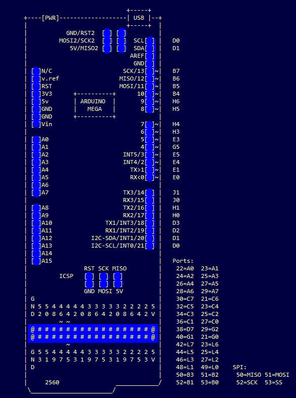
This is a snippet from a recent project. The sketch starts out with comments that set-out how the hardware is setup, this helps me a lot when I have to look at it again in a years time. Its also great if I want to share the code, as people don’t need to dig-around in the code to see how to connect the arduino to other devices.
/*

                                      +-----+
         +----[PWR]-------------------| USB |--+
         |                            +-----+  |
         |           GND/RST2  [ ] [ ]         |
         |         MOSI2/SCK2  [ ] [ ]  SCL[ ] |   C5
         |            5V/MISO2 [ ] [ ]  SDA[ ] |   C4
         |                             AREF[ ] |
         |                              GND[ ] |
         | [ ]N/C                    SCK/13[A] |   B5
         | [ ]v.ref                 MISO/12[A] |   .
         | [ ]RST                   MOSI/11[A]~|   .
         | [ ]3V3    +---+               10[ ]~|   .
         | [ ]5v     | A |                9[ ]~|   .
         | [ ]GND   -| R |-               8[B] |   B0
         | [ ]GND   -| D |-                    |
         | [ ]Vin   -| U |-               7[A] |   D7
         |          -| I |-               6[A]~|   .
         | [ ]A0    -| N |-               5[C]~|   .
         | [ ]A1    -| O |-               4[A] |   .
         | [ ]A2     +---+           INT1/3[A]~|   .
         | [ ]A3                     INT0/2[ ] |   .
         | [ ]A4      RST SCK MISO     TX>1[ ] |   .
         | [ ]A5      [ ] [ ] [ ]      RX<0[ ] |   D0
         |            [ ] [ ] [ ]              |
         |  UNO_R3    GND MOSI 5V  ____________/
          \_______________________/

		  http://busyducks.com/ascii-art-arduinos
*/

//------------------------------------------------------------------
// [A]		Adafruit music shield
//------------------------------------------------------------------
// Connect CLK, MISO and MOSI to hardware SPI pins.
// SPI Clock, shared with SD card
#define CLK_PIN (13)
// Input data, from VS1053/SD card
#define MISO_PIN (12)
// Output data, to VS1053/SD card
#define MOSI_PIN (11)

// VS1053 reset pin (unused!)
#define SHIELD_RESET_PIN  (-1)
// VS1053 chip select pin (output)
#define SHIELD_CS_PIN     (7)
// VS1053 Data/command select pin (output)
#define SHIELD_DCS_PIN    (6)
// Card chip select pin
#define CARDCS_PIN (4)
// VS1053 Data request, ideally an Interrupt pin
#define DREQ_PIN (3)

//------------------------------------------------------------------
// [B]		WS2811 LED stip
//------------------------------------------------------------------
#define LED_STIP_PIN  (8)

//------------------------------------------------------------------
// [C]		Servo Motor
//------------------------------------------------------------------
#define SERVO_PIN (5)
Related Projects (based on this work)
- I modified a version of this for markdeep and made it available for download here.
- There is a unofficial mirror (by vanderZwan) of the markdeep work here
- A console version, by paulfantom, for terminal users is available here.
Our markdeep version (click image to download)
Stay Up To date and Provide Feedback
- Contribute to the project on https://github.com/busyDuckman/ascii-art-arduinos
- I will check back on the facebook page for any comments, like the page to stay up to date.
- I set up a redirected URL http://busyducks.com/ascii-art-arduinos that is both the CC-BY attribution line, and will always redirect to the latest version of these ascii art arduinos.